Resistance and Power Requirements calculated for any Maxsurf design
Please click here to contact us for more details.
Wake and Power Prediction
Maxsurf Resistance estimates the resistance and power requirements for any Maxsurf design using industry standard prediction techniques.
Resistance Features
• Interactive interface
• Automated hull measuring
• Multiple analysis methods
• Multihulls using Slender Body method
• Planing vessels
• Workboats
• Ships
• Yachts
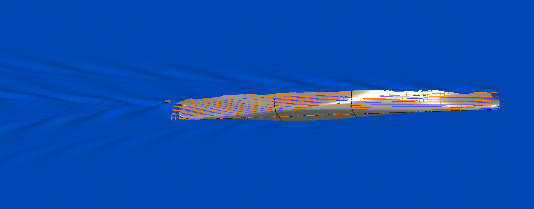
Automatic hull measurements from your Maxsurf model
You can apply the proven regression methods and potential flow calculations for slender hulls in Maxsurf Resistance to produce resistance curves and wake calculations
It supports resistance prediction calculations for a wide range of monohulls and multihulls.
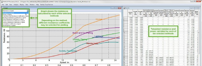
Various algorithms can be applied for estimating hull resistance.
These are divided in different groups dependent on the type of hull
- Method for planing hulls
- Method for displacement ships
- Method for yachts
- Analytical method
Note that that resistance prediction is not an exact science. The algorithms implemented in Maxsurf Resistance, while they are useful for estimating the resistance of a hull and are generally useful for correctly ranking similar design alternatives, they may not provide exact results.
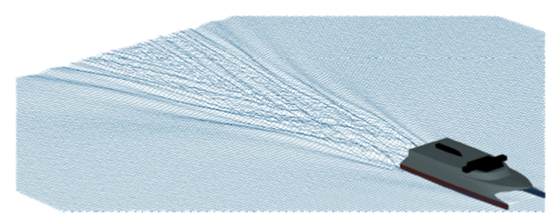
Analytical methods for slender hullforms which do not have suitable regression methods . This is particularly relevant to multihulls but may also be applied to slender monohulls and also several vessels sailing in convoy.
The Analytical formulation can also be used to evaluate the far-field wake generated by the vessel(s)
Automatic hull measurements from your Maxsurf model
Maxsurf designs may be read in to Maxsurf Resistance and automatically measured to obtain the required parameters.
Alternatively you can type in the parameters avoiding the need for an existing Maxsurf design file
Maxsurf Resistance checks that entered data is within the valid ranges for the selected methods.
Acceptable values are displayed in black, if they are too low they will be displayed in red with the words (low), and if they are too high they will be displayed in orange with the word (high).
Data may also be edited so as to gain insight into the sensitivity of each parameter.
However because most parameters are interdependent (eg changing the length will most likely result in a change of displacement or per haps half angle of entrance etc for a real vessel) It makes more sense to vary the actual model in the Modeler parametric variation tool and then measuring that new vessel. Of course this can all be automated using the Maxsurf automation interface and VBA macros, making it very easy to determine the resistance of a systematic series of hullforms derived from a parent vessel.