Please click here to contact us for more details.
Stability features extra detail
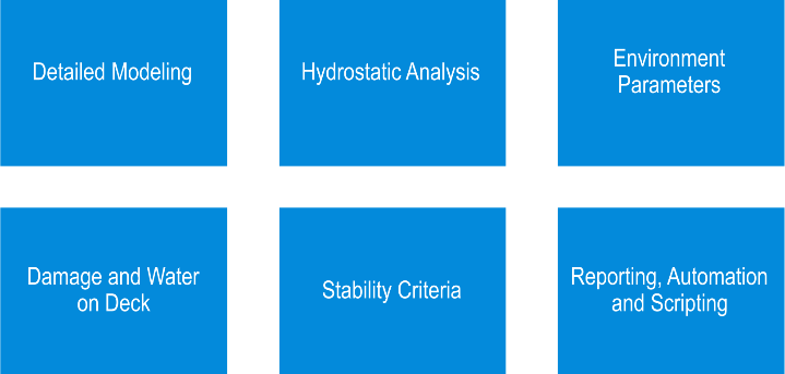
We can now look at some of the different aspects of the Stability features extra detail
1.Detailed modeling vessel components (rooms, loadcases, damage, keypoints*, etc)
2.Different types of hydrostatic analyses which can be performed
3.Environmental parameters which modify the analysis (wave-form, grounding)
4.How to include damage and water on deck (Stockholm agreement)
5.Assessment of stability criteria and code-checking
6.Reporting and automation** capabilities
* Keypoints are locations on the vessel of special interest, such as downflooding points, embarkation points, immersion points, etc. And are often used in stability criteria and code-checking
** Automation refers to the ability of running Maxsurf modules from another program: for example a VBA Macro in MS Excel (VBA=Visual Basic for Applications)
Detailed modeling involves adding to the hull geometry defined in Modeler to provide a sufficiently detailed description of the vessel to be able to perform the hydrostatic stability analyses.
Note Maxsurf is parametric and concurrent. So modifications may be made without having to redraw everything.
These additional data are:
- Layout and geometry of tanks and compartments (collectively known as “rooms”)
- Sounding pipes for tanks;
- Mass and center of gravity (loadcases);
- Keypoints (such as downflooding points)
- Damage cases (lists of rooms which should be considered flooded);
- Cross-flooding devices;
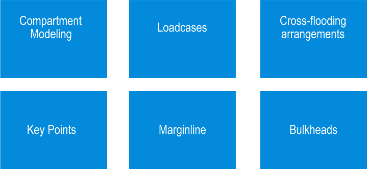
Compartment modeling
Automatic trimming to hull envelope
Simple definition from 6 planes
Complex shapes using linked parts
Complex shapes using NURBS surfaces
Default fluid
Sounding pipes
Tanks, compartments and non-buoyant volumes are referred to collectively as “Rooms”
Tanks can contain a liquid cargo and are automatically included in the loadcases
Compartments are watertight spaces in the vessel which may be flooded with seawater in a damage case
Non-buoyant volumes are spaces which are permanently flooded with seawater (even in the intact condition) for example: thruster tunnels, water-jet ducts, moon-pools, etc
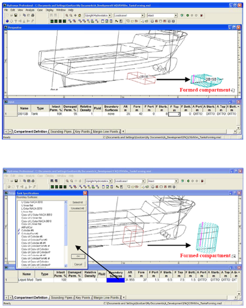
Rooms are automatically “formed” by clipping the room boundary to the hull envelope (shell thickness, defined on a surface-by-surface basis in Modeler may be included so that the buoyant hull goes to the outside of the shell and rooms go to the inside of the shell.
The simplest way of defining a room is to specify 6 limit-planes: forward, aft, top, bottom, port, starboard. This cuboid is then automatically clipped to the hull envelope.
More complex rooms can be built up by linking several of these clipped cuboids (they do not have to be adjacent but will always share a common fluid plane)
For rooms of any shape, NURBS surfaces created in Modeler can be used to define the room boundary (eg cylindrical mud tanks, bow thrusters, water-jet ducts, etc)
For each tank a default fluid can be specified and this will be used when calculating the loadcase mass
Vertical tank sounding pipes (sounding tubes) are automatically created for all tanks, but these can be modified if desired, adding bends or making them inclined.
Loadcases
Loadcases
Loadgroups
Mass distribution
Formatting
Fluids
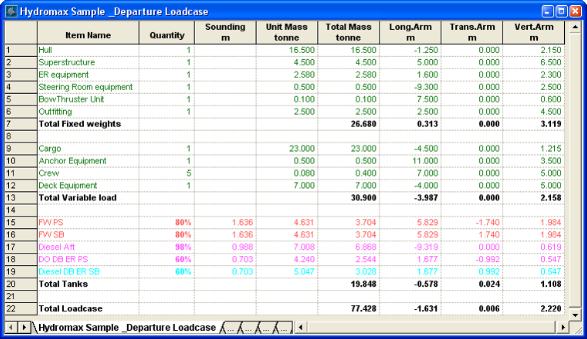
Loadcases are used to define a schedule of weights. A loadcase can then be selected and the vessel equilibrium position with that load and cg applied can be calculated, for example.
A loadgroup is a group of fixed weights that can be then included as a single row in one or more loadcases. A good example of this is the Lightship weight which can be defined in a loadgroup and included in several loadcases (e.g. Departure and Arrival conditions). Should any changes be required to the lightship, this is done in the Lightship loadgroup which will then automatically update the loadcases that include it.
Loadcases automatically include any tanks defined in the model and the amount of fluid in the tank can be specified as a percentage, a mass or a volume
For longitudinal strength calculations, the forward and aft extents of fixed loads must be specified so that the distributed load of the mass item can be calculated (a linear, trapezoidal mass distribution is used – more complex shaped mass distributions can be modelled by splitting up the fixed load into sub loads each with its own linear distribution).
The longitudinal distribution of the tank loads is automatically calculated from the section-area curve of the tank.
To make it more readable the loadcase can be formatted with blank lines and sub-totals and comments.
If required the default tank fluid can be overridden in each loadcase – this is useful for product carriers which may, at different times, carry different fluid cargos in the same tank
Cross-flooding arrangements
Pair of connected rooms
Locations
Direction of flow
Pipe dimensions
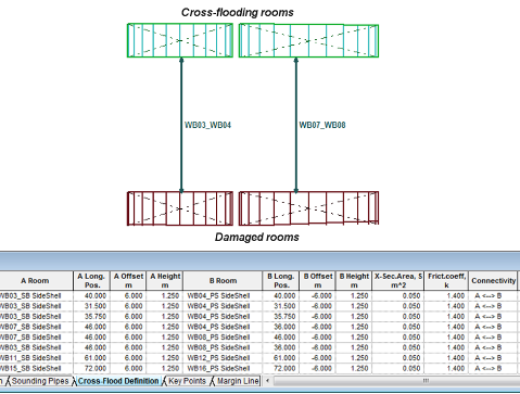
Cross-flooding arrangements can be defined for assessing the time for cross-flooding and intermediate stages of flooding a prescribed time intervals.
This requires a definition of:
the pair of rooms that are connected
the location of each end of the pipe
the direction of allowable flow (both ways or one way only)
the flow properties of the pipe (cross-sectional area and friction coefficient)
Key points
Down-flooding
Water on Deck
Stability Criteria
Usage – intact or damage
Key points are used to define a variety of important locations on the vessel
Depending on the type of keypoint, they have different uses and properties
They can be used for:
Determining the downflooding angle
Calculating water on deck (Stockholm agreement)
Used for stability criteria, eg freeboard or immersion angle of a certain type of key point
Outflow points for spilling tanks (tanks which lose their fluid when inclined)
Keypoints can be optionally ignored for either intact analyses or damaged analyses
Depending on the analysis type being performed, the immersion and emergence angle of each point is calculated or their freeboard.
Margin line and deck edge
Automatic calculation
Manual editing, snapping to hull
Stability criteria
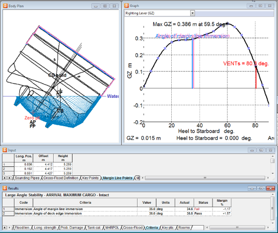
The margin line and deck edge points are similar to keypoints except they are treated as a group.
They are calculated automatically by finding the deck edge of each section and then placing the margin line 3 inches below this point
Of course it can be manually edited by specifying a new height and then snapping the point back on to the hull surface
The margin line and deck edge immersion angles and freeboards can be used to calculate stability criteria
Bulkheads and Modulus
Bulkheads:
Floodable length curve
Modulus:
Longitudinal Strength allowable Shear Force and Bending Moment limits
Transverse bulkhead locations can be defined and these may be displayed on the floodable length curve
Limiting values of shear force and bending moment can be specified for different positions along the hull and these can be displayed on the longitudinal strength diagram.
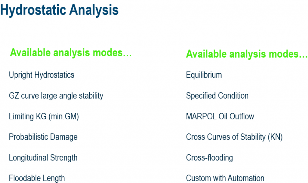
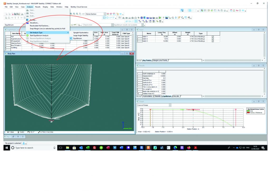
The following analysis modes are available in Stability
As well as all the built in analyses, these can be further customized through the COM (Component Object Model) automation interface using, for example, a VBA macro in MS Excel
Upright hydrostatics
Inputs
–Draft or displacement range
–Fixed trim (upright, zero heel)
–VCG if known
Results
–Selected hydrostatic data
The Upright Hydrostatics analysis calculated the vessel’s hydrostatic properties at a range of draughts or displacements at specified trim and zero heel
If known, the VCG can be specified in which case values such as KG and GM are calculated taking this into account
These data are available in tabulated and graphical format, both of which are user-customizable in terms of the data which are displayed
In addition (as with most analyses) the sectional area curve at each condition can be displayed
GZ curve (large angle stability)
Inputs
- Heel angle range
- Loadcase (displacement + CG)
- Trim –
fixed or free - Damage, Water on deck
- Stability criteria
Results
- GZ curve
- Stability criteria
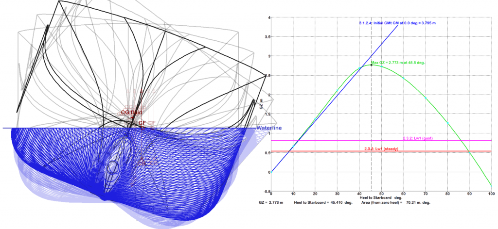
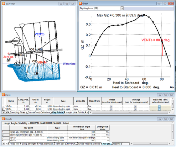
The large angle stability analysis calculates the vessel righting moment at a specified range of heel angles (the full heel range from -180 to 180 may be computed in case of vessel asymmetry)
The vessel mass and displacement is specified by choosing a loadcase (or load group)
The vessel may be free to trim in which case the longitudinal balance of CG an CB is evaluated or trim may be fixed to a specific value
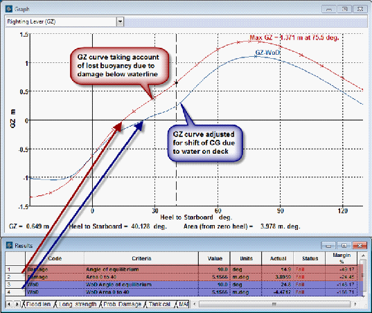
The GZ curve can be evaluated for the intact vessel or for a selected damage case.
The computed data are tabulated and graphed
Stability criteria based on the properties of the computed GZ curve can be calculated and their pass/fail status displayed (as well as all intermediate data)
Where appropriate the stability criteria are included on the GZ curve (heeling arms, GMt, etc)
Limiting KG (min. GM)
Inputs
- Displacement range
- Heel angle range
- Initial trim or CG
- Trim – fixed or free
- Critical criteria
Results
- Max KG, min. GM
- Limiting criterion
Limiting KG analysis calculates the maximum VCG that the vessel can have at a given displacement and still pass the selected GZ-based stability criteria
(sometimes also referred to as the minimum GM)
Inputs:
A range of displacements for which the maximum VCG (minimum GM) should be calculated and the LCG or initial trim to be used.
The range of heel angles at which to calculate the GZ curve (this should be of sufficient range for the selected GZ criteria) – other data as per GZ curve calc: fixed/free trimming
The GZ-based criteria that should be checked
Results:
For each displacement:
max. KG (min. GM) such that criteria are just passed
Which criterion was the one the critical one.
Possibility of running for intact or damaged vessel
Possibility of doing batch analysis for each individual criterion selected
Algorithm:
Binary search to find VCG that just causes criteria to fail.
Assumes lowering VCG will make it more likely for the criteria to pass (this is not always the case in some unusual situations)
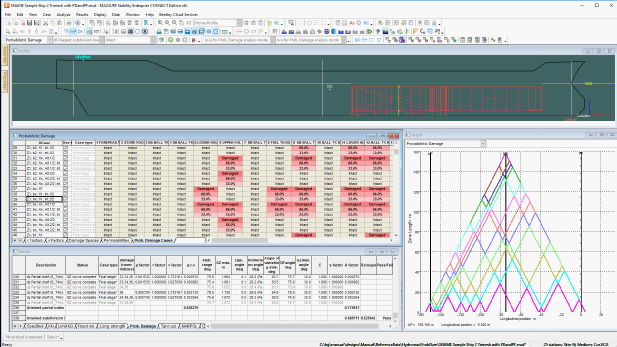
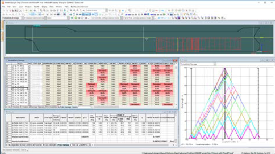
Probabilistic Damage
Inputs
- Loadcase for required drafts
- Heel angle range
- Trim –
fixed or free - Probabilistic parameters, criteria
- Subdivision zones
- Damage –
final and intermediate cases
Results
- Attained index
- Details of each stability analysis
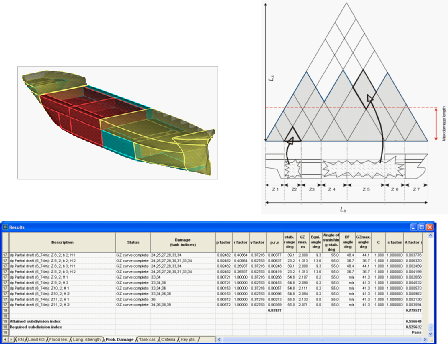
Compute probabilistic damage attained index for dry cargo and passenger vessels according to:
Harmonised method:
Resolution MSC.421(98) included
RESOLUTION MSC.281(85) 2008: EXPLANATORY NOTES TO THE SOLAS CHAPTER II-1 SUBDIVISION AND DAMAGE STABILITY REGULATIONS
RESOLUTION MSC.245(83) 2007: RECOMMENDATION ON A STANDARD METHOD FOR EVALUATING CROSS-FLOODING ARRANGEMENTS
RESOLUTION MSC.216(82) 2006: ADOPTION OF AMENDMENTS TO THE INTERNATIONAL CONVENTION FOR THE SAFETY OF LIFE AT SEA, 1974, AS AMENDED
older similar documents
MSC.1/Circ.1226 2007: INTERIM EXPLANATORY NOTES TO THE SOLAS CHAPTER II-1 SUBDIVISION AND DAMAGE STABILITY REGULATIONS
RESOLUTION MSC.194(80) 2005: ADOPTION OF AMENDMENTS TO THE INTERNATIONAL CONVENTION FOR THE SAFETY OF LIFE AT SEA, 1974, AS AMENDED
Or Older method:
RESOLUTION MSC.19(58) 1990: ADOPTION OF AMENDMENTS TO THE INTERNATIONAL CONVENTION FOR THE SAFETY OF LIFE AT SEA, 1974. Part B-1 – Subdivision and Damage Stability of Cargo Ships. Regulation 25-1
——————————————————————————————————————
Inputs:
Displacements and CG (trim) using loadcases/loadgroups:
Deepest subdivision draft (summer loadline) Loadcase
Partial subdivision draft Loadcase
Light service draft Loadcase
Heel angle range to be tested
Trim: fixed or free-to-trim
Other probabilistic damage analysis parameters
Stability criteria options for Survivability Index calculation
Subdivision zones (longitudinal, transverse and vertical subdivision boundaries)
Damage: breached (flooded) rooms (tanks+compartments) due to damage in different zones: Final damage and partial flooding at intermediate stages, including cross-flooding
—————————————————————————-
Results:
Attained Subdivision index
Full details of stability calculations (GZ curve, survivability index, etc) for each draught and damage condition.
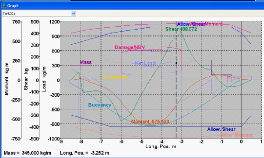
Longitudinal Strength
Inputs
- Loadcase
- Damage
- Grounding
- Waveform
Results
- Loading
- Shear force
- Bending moment
Inputs
Loadcase: longitudinal mass distribution
Damage (optional)
Grounding (optional)
Waveform (optional)
Results
Vessel is balanced at equilibrium, then the net longitudinal loading, shear force and bending moment distribution is computed and compared with user-specified curves of limiting shear force and bending moment
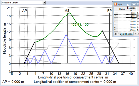
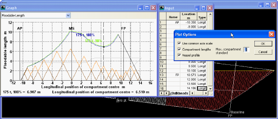
Floodable Length
Inputs
- Permeability range
- Displacement range
- Initial trim or CG
- Immersion criterion, freeboard of margin line or deck edge
Optional additional criteria
- min. GM, max. Trim
Inputs
Range of permeabilities
Displacement range and CG (specified or from initial trim)
Immersion criterion (i.e min allowable freeboard of margin line or deck edge)
Optional criteria (e.g. min. GM, max. trim)
Results
Computed floodable length curve for each permeability + displacement combination (max floodable length that just meets criteria)
Tabulated data
Graphs optionally including compartment lengths (for any number of adjacent flooded compartments) and vessel profile
Vertical and horizontal scale can be locked
Enhanced intermediate stages of flooding functionality capability.
- Any number of intermediate stages with partial flooding levels can be specified for each damage scenario (in addition to the final stage which is automatically generated).
Equilibrium
Inputs
- Loadcase
- Damage
- Grounding
- Waveform
Results
- Hydrostatics
- Freeboards
- Flooding / spilling in tanks
Inputs
Loadcase
Damage (optional)
Grounding (optional) – note heel is restrained when grounding is specified (ie vessel fixed upright)
Waveform (optional) – waveform must be along the longitudinal axis of the vessel
Results
Vessel balanced: displacement vs volume and Centre of Gravity vs Centre of Buoyancy
Hydrostatic properties
Freeboards to keypoints and keylines (margin line + deck edge)
Equilibrium-based stability criteria
Flooded volumes in damaged rooms (and Centre of floodwater)
Immersed sectional area curve
If grounding is specified, grounding reactions are computed
If waveform is specified, these data are calculated for a number of different wave-crest locations along the hull.
Specified Condition
Inputs
- Drafts or displacement
- Trim or LCG
- Heel or TCG
- VCG
- Damage
Results
- Hydrostatics at specified condition
Useful for inclining experiment analysis

Specified Condition analysis is very similar to the Equilibrium (ee-kwuh–lib-ree-uh m) analysis,
However the vessel condition can be specified by either: mass and center of gravity; or draughts and heel; or a combination of the two methods
Results calculated are the hydrostatics at the specified condition (including sectional area curve). These types of data can be quite useful when performing an inclining experiment or lightship survey as the displacement and centre of buoyancy are easily calculated from the draught measurements.
MARPOL
Analysis
- Resolution MEPC.141(54),
Regulation 12A: Oil fuel tank protection - Resolution MEPC.117(52),
Regulation 23: Accidental oil outflow performance
Inputs
- Bottom and side damage tanks
Results
- Outflow parameter and pass/fail statu
The MARPOL analysis can calculate the outflow parameter according to:
Resolution MEPC.141(54), Regulation 12A: Oil fuel tank protection
or
Resolution MEPC.117(52), Regulation 23: Accidental oil outflow performance
Inputs required include the Deepest loadline draft (d_S) and Lightship draft (d_L) as well as a list of tanks to include and whether they should be considered to have side or bottom damage.
The result is the actual and allowable oil outflow parameter and the pass/fail status
Ass well as all intermediate calculation data
Cross curves of stability (KN)
Inputs
- Displacement range
- Heel angle range
- Initial trim or CG
- Trim –
fixed or free - Estimated VCG
Results
- Cross curves of stability
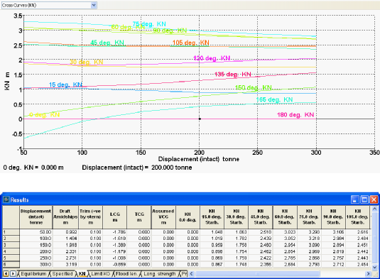
KN curves or Cross-curves of stability can be calculated for a range of displacements at specified heel angles
The LCG is either specified explicitly or derived from the initial trim at each displacement
If free-to-trim calculations are performed the 2nd order effect of VCG on trim can be approximately accounted for by specifying an estimate of the VCG (rather than assuming the Keel)
Cross-
Inputs
- Initial damage
- Intermediate stage times
Results
- Flooded conditions
- Time for complete cross-
flooding
Calculation of intermediate stages of cross flooding and final cross-flooded condition
intermediate stages are computed using the method given in
RESOLUTION MSC.362(92) 2013: REVISED RECOMMENDATION ON A STANDARD METHOD FOR EVALUATING CROSS-FLOODING ARRANGEMENTS
Similar older documentation
RESOLUTION MSC.245(83) 2007: RECOMMENDATION ON A STANDARD METHOD FOR EVALUATING CROSS-FLOODING ARRANGEMENTS
RESOLUTION A.266(VIII) 2007: RECOMMENDATION ON A STANDARD METHOD FOR ESTABLISHING COMPLIANCE WITH THE REQUIREMENTS FOR CROSS-FLOODING ARRANGEMENTS IN PASSENGER SHIPS
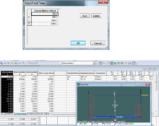
Inputs:
The initial damage before cross-flooding is specified in a damage case
The cross-flooding arrangement definition is used to determine which rooms will be cross-flooded
The times at which the intermediate stage of cross-flooded condition should be calculated can be specified (eg 60s and 10mins)
Results:
Flooded conditions
Before cross-flooding
At intermediate times
After complete cross-flooding
Time for complete cross-flooding
Stability: Time for cross-
Verify compliance with IMO Resolution MSC.362(92) by calculating time to cross-
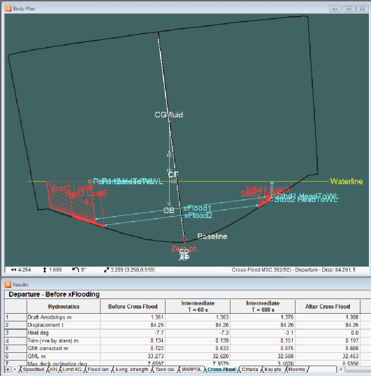
A new analysis, following the procedure outlines in IMO Resolution MSC.362(92) Revised Recommendation on a Standard Method for Evaluating Cross-Flooding Arrangements, has been added to this version of MAXSURF Stability. Cross-flooding devices connecting pairs of rooms are defined for the model. The analysis takes an initial damage condition and evaluates the final cross-flooded condition, as well as the time to achieve full cross flooding using the procedure in MSC.362(92). Specify any number of intermediate times, e.g. 60s and 600s, and the vessel condition, including room flooding level, will be computed at these time-steps. The analysis takes into account multiple pairs of cross-flooding rooms, and automatically finds the volume of cross-flooded fluid for each pair of rooms at each time step. View the vessel condition graphically at each immediate time step, as well as pre and post complete cross-flooding. Full vessel properties including flooding volumes and centers are tabulated for all the conditions.
Cross-
Include the effect of spilling liquid cargo or ballast from tanks during stability analyses
Use key-
View remaining fluid in tanks at each phase of the analysis
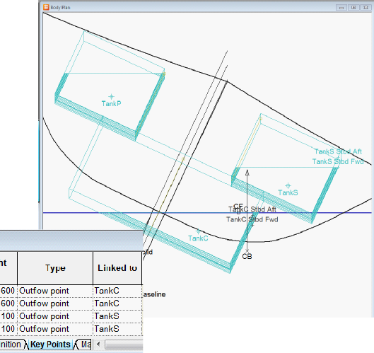
Spilling of liquid cargo from tanks has been added to this version of MAXSURF Stability. Select outflow points to be connected to spilling tanks to determine the maximum height of the fluid in each of these tanks based the lowest outflow point. Each stage of the analysis is considered independently with the tank spilling from its originally filled level as specified in the Loadcase. You can select an option to allow the tank to refill should the lowest outflow point be immersed below the external seawater level. View a complete set of results for each room for Equilibrium analysis, and for each room for all heel angles in the case of a Large Angle Stability analysis. Results include the centroid and mass of cargo (in the case of a filled tank), buoyancy (in the case of damaged rooms or permanently flooded spaces) and water on deck (in the case of spaces defined as having water on deck applied).
Customized Analysis with Automation
- Stability analysis engine
- VBA Scripting / automation
- Extend existing analyses
- Batch analysis

Stability analysis engine
VBA Scripting / automation
MS Excel
MS Word
etc. (Any COM enabled application)
Extend existing analyses
Batch analysis: automated run of multiple analyses one after the other with no User input
Example of Customized Analysis
with Automation
By University of Strathclyde, Glasgow
with involvement of
Lloyds Register and RINA.
A tool has been developed at the Department of Naval Architecture, Ocean & Marine Engineering at the University of Strathclyde.
It is based on a code written in MS VBA in MS Excel using the automation tools of the Maxsurf suite (Maxsurf
Modeler 2014).
https://strathprints.strath.ac.uk/57360/1/Liu_etal_IMDC_2015_Prevention_of_parametric_rolling_through_multi_objective_optimisation.pdf
This project was funded by Lloyd’s Register. All internal information relevant to second generation of intact stability was kindly provided by Royal Institution of Naval Architects. The support from Lloyd’s Register and Royal Institution of Naval Architects was gratefully acknowledged.

Environment Options
- Fluid Density
- Waveform
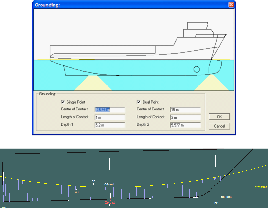
- Grounding
- Hog / Sag
A range of “environmental” parameters may be applied as additional analysis options.
Seawater density (as well as densities of other standard fluids which may be included as cargo or ballast in tanks)
Waveform: longitudinal waveform of specified wavelength and height (the phase: position of crest can also be varied). Trochoid (troh-koid) or sine waveform can be selected
Grounding can be specified for Equilibrium and Longitudinal strength analysis. Single or double point grounding may be defined. During grounding the vessel is constrained in heel.
The effects of hog or sag can be approximated by distorting the waterline from a flat waterline. The hydrostatics will then be computed to this distorted waterline.
Damage and Water On Deck (Stockholm)
Intact and Damage
Partial flooding
- Limit flooding to percentage of fully-
flooded - Common waterline
- Individual waterline
Spilling
Water On Deck
Damage in MAXSURF Stability is always accounted for by the lost buoyancy method.
Damage is specified by “damage cases” which specify the flooded condition of each room. Rooms can be specified to fully flood (up to their maximum capacity) in which case the flooded waterline in the room will match the external seawaterline; otherwise to specify intermediate flooding the maximum percentage of the room capacity can be specified. For example if the flooding is to be limited to a maximum of 20% of the full room capacity, then 20% should be specified as the partial flooding factor.
Furthermore, when two or more rooms are specified for partial flooding they can be specified to share a common waterline or have separate flooded waterlines.
For tanks carrying liquid cargos, these may be defined as losing all their cargo when damaged (cargo drop out) or retaining their cargo; in either case their buoyancy (boi–uh n-see) up to the damage waterline is lost.
Tanks carrying liquid cargo may be allowed to spill their contents, this is done by specifying an outflow point (or points) connected to the tank.
During Large angle stability analysis each heel step is considered independently (so that spilling is independent of the sequence of heel angles tested)
Water on deck: Stockholm Agreement
MCA MSN 1790 (M) “Agreement Concerning Specific Stability Requirements for Ro-Ro Passenger Ships Undertaking Regular Scheduled International or Domestic Voyages between European Ports”
This option is available for Large Angle Stability analysis only. Following guidance from MCA (Maritime and Coastguard Agency, UK) The GZ curve is calculated as normal then for each heel angle the volume of water on deck is calculated and its effect on righting centre of gravity and righting moment calculated (the vessel is not rebalanced to the increased displacement and change of CG). These data are reported as a modified GZ curve and stability criteria may be calculated using this modified GZ curve if required).
Stability Criteria
Parent
- Criteria calculations from GZ curve
- Heeling arms of various types
- Calculations such as IMO rollback angle
Predefined customized criteria
User-
Comprehensive reporting of intermediate calculations
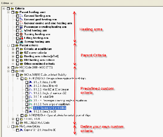
Comprehensive Stability Criteria are available in MAXSURF Stability
They are based on the concept of “Parent” criteria which describe specific calculations (eg the area under the GZ curve)
Users may make copied of these “Parent” criteria and customise the parameters used for the criterion (eg the integration limits for the area under the GZ curve)
As well as Criteria, there are also “Heeling Arms” and “Calculations” which may be copied and customised and referenced into criteria.
“Heeling Arms” can take several forms (eg Passenger Crowding, Wind heeling, etc); Calculations cover many common calculations such as IMO roll back angle for “Wind and Waves criterion”.
As well as being able to customize criteria, MAXSURF Stability installs a wide range of common stability criteria such as IMO
The format of how criteria are included in the stability report is customizable (compact mode, just reporting pass/fail status or verbose mode, including all intermediate calculations)
Reporting
MS Word or RTF
Customizable reporting based on MS Word templates
Report generation using existing results database
Automation for fully customizable reports
Batch analysis
Various reporting options exist in Stability, these are designed to assist you in producing reports in customisable formats to meet specific requirements.
The report can be sent to MS Word (preferred option) or to the RTF (rich text format) report window in Stability itself.
When reporting directly to MS Word the is the option of specifying a MS Word template document to be used. This enables customisation of the data, tables and graphs which are included in the report for each analysis type.
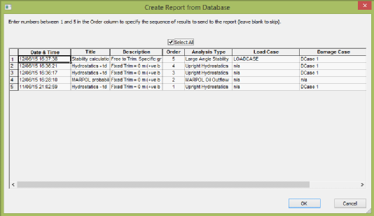
A recent addition to Stability is the ability to generate a report from a database containing previously calculated results, this means that the report template can be modified and the report regenerated very quickly (using the pre-calculated results in the database)
A final option for fully-customisable reports is the ability to drive Stability from a MS Word (or MS Excel) VBA (Visual Basic for Applications) Using this approach you can use VBA and the Stability automation interface to run specific analyses then extract and format the data required in your report
Stability also has a build-in batch analysis option which simplifies the task of running a common selection of analyses. Stability features extra detail.
Saving and reloading results from SqliteDB
Results may be stored in a SQlite database as they are created. Allowing:
Review of previous calculations
Generation of reports from selected previously calculated results (without the need to re-
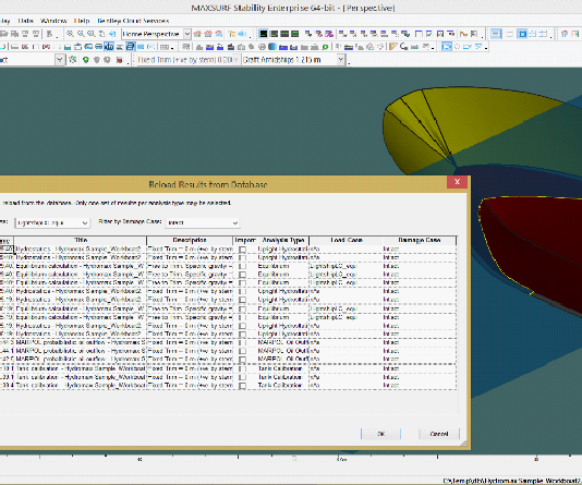
Results from all MAXSURF Stability analyses can now be automatically stored in a SQL database. At the click of a button you can restore the results, saving time previously spent re-analysing. All settings related to the analysis run are also stored and reloaded, making it easy to review parameter settings and either reproduce results or recalculate them for slightly varied parameters. This greatly facilitates report generation by allowing you to select which analyses should be included in the report and in what order. Modify the report settings (table format, report templates) and regenerate the report in seconds using the results stored in the SQL database. Turn on options to auto-load the most recent results when you open a model to continue where you left off the last time you edited the model, or to reload results as you toggle between current Loadcases and Damage Cases.
Use these powerful functions to quickly and easily access any set of results and analysis settings from the design process without having to perform time consuming reanalyses, or re-enter analysis settings. A simple SQL database is used enabling expert users to interact with the results directly.
In theory only available disc space limits the number of analysis results that may be stored in the SQLdatabase, however access performance may deteriorate if too many sets of results are stored in the same database
MAXSURF Stability – enhanced SOLAS 2009 probabilistic damage analysis
Perform probabilistic damage analysis with enhanced intermediate stages of flooding functionality capability.
Improvements have been made to the way that intermediate stages of flooding are dealt with in MAXSURF Stability’s probabilistic damage analysis.
Any number of intermediate stages with partial flooding levels can be specified for each damage scenario (in addition to the final stage which is automatically generated). This can be used to simulate partial cross-flooding as well as intermediate, partial flooding when instantaneous flooding of the whole space cannot be assumed. The damage scenarios are automatically combined depending on the number of adjacent zones to be investigated as well as the different vertical and transverse extents of damage that must be considered. The intermediate survivability factors for all intermediate cases are assessed automatically and the worst condition automatically selected.
Videos on Probabilistic Damage Analysis
Introduction – This video is an introduction to the basic concepts of Probabilistic Damage Stability.
Input Global Data – Before you can run Probabilistic Analysis, you need to enter in global data.
Input Parameters – This video takes a look at input parameters for zones of damage and permeabilities.
Setup Stability Criteria – This video shows how to set up the stability criteria used to calculate the S probability of survival.
Correct Tips – This video offers tips on verifying that you have set up your damage stability correctly. It also will show you how to set up the criteria you will use for damage stability.
Analysis Results – This video explains how to review results of Probabilistic Damage Analysis.