A short series of posts to highlight some useful features that you might not be aware of.
Often additional options for a command are exposed when you hold down the shift key.
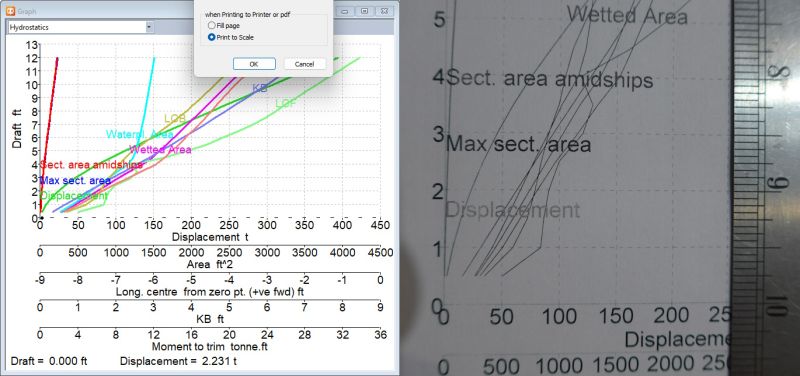
Printing graphs to a scale that can be easily measured was introduced well over 20 years ago. Holding down the shift key whilst doing the print preview of the Graph window will prompt you for an option to “Print to Scale”. For the next release, this option will be more readily accessed in the “Graph Options” dialog.
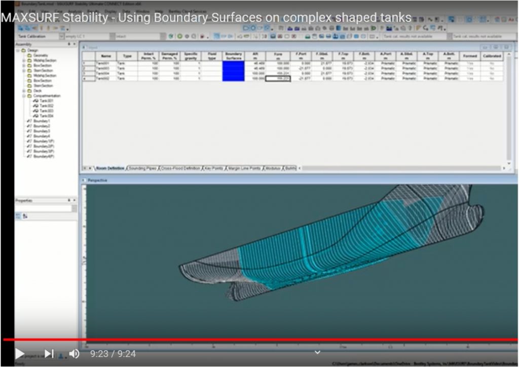
MAXSURF Stability – Using Boundary Surfaces on complex shaped tanks.
Most tanks in MAXSURF Stability are defined using parameters that define their extents. However if you have a complex shape like a LNG sphere, cylindrical mud tank or just a tapered space then you’ll want to use boundary surfaces. This video by James of Maxsurf Tech Support talks through the process – watch here
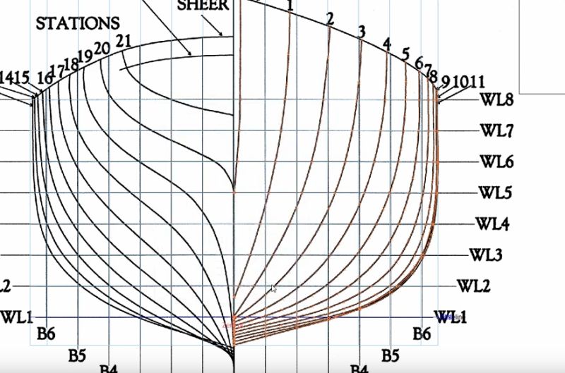
Digitizing in Maxsurf Modeler
Sometimes when modeling existing vessel where a digital lines plan is not available, it is useful to add markers in the Maxsurf model which trace the hull sections. If you have a scanned image of the lines plan this can be loaded as a background image and used as a basis for digitizing. A useful feature when digitizing in the Body Plan view is that the longitudinal coordinate (depth in the view) is taken from the Current section. So if you setup your section spacing first, you can select the station you are going to digitize in the Inset Box. Another handy feature is that for some commands, such as Add Markers, you can repeat the last command by using the Enter key. This feature works for a few selected commands (since it could be quite catastrophic to have Delete work in this way!) For more details on digitizing from scanned images we have a video explaining this and more: https://lnkd.in/d3btdswz
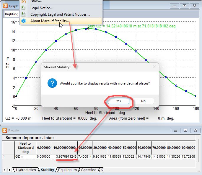
Pat Couser wrote: More decimal places?
Here is a feature that we haven’t really advertised but some people (like me?) might find useful. Normally the number of decimal places displayed in the tables and dialogs is fixed and depends on the units being used. Sometimes it is desirable to have more decimal places displayed, for instance when copying data to a spreadsheet for further analysis. To do this click on the Help | About menu item with the shift-key held down, you will then be prompted to turn on (or off) the display of more decimal places (before the normal About dialog is displayed).
Please let me know if you find this feature useful and should be more easily accessible in the UI. If you are scripting through the COM API you can access this option in the Application object TableOutputMinNumDecimalPlaces property. In Multiframe, the units dialog allows you to specify exactly how many decimal places and the format for each type of measurement in the View | Units dialog.
Rhino 3D Import.
The Rhino file format does not contain the full trimming information required by Maxsurf to recreate the trimming. Most file formats, 3dm, dgn, iges only contain parametric curves on the trimmed surface and then flags for which parts of that surface are trimmed – there is no description of the origin of those curves. Maxsurf trimming works on dynamically calculating the intersection of trimming surfaces or projected trimming curves onto the surface to be trimmed. For this reason we cannot import trimming information from these file formats.
We always recommend working in Maxsurf modeler first and then exporting to Rhino (or other CAD) for downstream detailed design, and not the other way around.


Stability
Downflooding points are one type of “Key Point” which are used for many different things. Only points are supported (not lines or surfaces). Please refer to the manual for full details
Structure module
– A question was ‘How to export stringers and stringer cutouts (when exporting the stringer cutouts in Rhino / AutoCAD, we are losing the radius / the fillet of the cutout)’
Reply is: Which export are you using? DXF export from the part drawing window should be accurate. Note that simple polylines are used, not polylines with radii included because the feedback we were receiving indicated that embedding radii in the DXF polylines caused problems with cut paths.


For the next release there are improvements to the mesh export of parts, using the minimum number of triangles whilst retaining the accuracy of the perimeter polyline


Non constant flange section
How to generate primary members with non constant flange section ?
You should add a “Longitudinal Girder”
You can then specify the flange width at each point on the Girder


Python is an ideal programming language for driving hashtag#Maxsurf applications through their Automation API (of course there are several alternative which can also be used: VBA; VBscript; c# etc). In-house here at hashtag#BentleySystems we tend to use Python and VBscript. Python has many useful libraries, eg: https://lnkd.in/dQjspUvM which makes it very simple to create MS Excel workbooks with data and charts extracted from Maxsurf. We are gradually adding more Python samples that ship with Maxsurf. If you have any ideas you’d like to see coded up, please let us know.
Docking calculations using Maxsurf Stability
Introduction
Although Maxsurf Stability does not have a dedicated docking analysis mode, upright stability and longitudinal strength calculations can be performed using grounding to achieve the same results. Furthermore detailed large angle stability of critical conditions can be simulated by the addition of the grounding reaction force to the loadcase.
Grounding
Maxsurf can define up to two grounding points. From a hydrostatic balance point of view, they are treated as point contacts. For the longitudinal strength perspective, a contact patch length can be specified for each contact point so that the grounding reaction force is distributed over a specified length of the vessel’s keel.
When using the grounding option, the vessel is constrained in heel and remains upright. However stability characteristics such as GM are computed and these include the effect of the grounding reaction and the virtual rise of the center of gravity.
Transverse stability
Large angle stability calculations at a range of heel angles may be computed for certain critical conditions, eg where the grounding reaction is at a maximum and the vessel is potentially at its least stable condition. To do this, it is necessary to turn off the grounding and add the grounding reaction forces to the loadcase. Since these are negative forces acting on the keel of the vessel, the VCG of the loadcase will be raised.
Procedure
Loadcase
The first step is to set the loadcase for the condition of the vessel when entering the dock. If longitudinal strength calculations are to be performed, then it is important that the loadcase includes the longitudinal distribution of the masses.
Equilibrium
A series of equilibrium analyses should then be computed with the grounding point(s) gradually moving upwards (to simulate the seawater being drained from the dry dock). The GM should be monitored to ensure that the vessel is stable in all conditions.
Longitudinal Strength
In parallel with the Equilibrium analysis at each step, it is possible to run a longitudinal strength calculation for each condition and to monitor the shear force and bending moments being applied to the hull girder. Note the limitation that only two grounding points can be defined.
Large Angle Stability
If any conditions are of particular concern from a hydrostatic stability point of view, eg very low or even negative GM, then a Large Angle Stability analysis can be performed to see how critical the condition is (if GZ is zero or negative for several degrees heel then it is likely that the docking plan will have to be modified.
Example
Initial condition
Here is an example docking of a frigate-like ship, free floating at the loadcase in which it will be docked.

Lightship mass distribution defined as a Loadgroup

Longitudinal Strength analysis for the free-floating vessel
Docking plan simulation
We can then add the keel block using the grounding dialog:

Specify the depth of the keel blocks below the DWL in the Grounding dialog
We can then incrementally reduce the depth of the keel blocks below the DWL to simulate the seawater being removed from the dock. We can run an equilibrium analysis at each step and record and plot the changes of important results as the vessel settles onto the keel blocks:

Table of key results for each depth of the keel blocks


Sometimes, depending on the vessel geometry and the exact grounding depths, but typically just as the second grounding point is about to make contact, Maxsurf Stability fails to find a solution and will display the dialog bellow. Normally it is just a question of reducing the problem to a single grounding point.


Reduce to single grounding point if convergence errors are encountered
If desired we can calculate the longitudinal hull girder bending shear force and bending moment in the longitudinal strength analysis

Longitudinal Strength analysis just before fwd part of vessel touches keel blocks
Changes to the loading condition
At each step, the vessel ballasting could be changed in the loadcase if this was specified in the docking plan.
Transverse stability
After doing the equilibrium analysis we obtain the grounding reactions

Grounding reactions in the ‘Displacement’ row of the Equilibrium results
We can switch to the Large Angle Stability analysis mode (grounding is automatically ignored) and then put the grounding reactions in as –ve Quantity masses in the loadcase:

New loadcase with grounding reactions applied
We can then calculate the GZ curve accounting for the grounding reactions (and compare with the free floating case, for example).

GZ for grounded vessel compared with that of the free-floating vessel
How to automate the generation of the stability booklet to speed up the damage analysis process.
There is a document which outlines the various levels of reporting Maxsurf Stability. Reporting in Maxsurf Stability
Further details are in the Manual
Automation is a good approach, I prefer to use Python and you can use the various libraries (such as xlxwriter) to create spreadsheets or documents. Or you can also access MS Word and Excel through their COM interfaces from the same script. I have used both methods.
There are some Automation samples shipped with Maxsurf. The majority are quite straightforward and are VBA macros in Excel or Word, more recently I have found Python to be more convenient and flexible.

There is a Python script available from Tech support.
The key thing is to set up the WordStylesEmptyTemplate.docx with the styles needed, especially for the table.
I’ve called the style “TableMS”, potentially you can have several and then modify the Python script to use different ones for different tables
The other thing is to set up the table formats in Stability manually – which columns and whether its vertical or horizontal etc and then to save this to “TableFromatAndLayout_formatted.json”
The same with the criteria – there is one set for intact and another for damage

Problem corrected May 2026: Large Angle Stability Analysis Error: Upper heel angle bound less than lower bound
| Product(s): | MAXSURF Stability |
| Version(s): | 25.00.02.339 |
| Area: | Stability analysis |
Problem
Stability Error: Upper heel angle bound less than lower bound (30° to 40°)
This typically happens when the software cannot establish a valid heel angle range because the upper bound becomes smaller than the lower bound (30°).
Common triggers include:
- First GZ peak occurring below 30°
- Downflooding (DF) point or margin line immersion below 30°
- Geometry issues such as incorrectly defined deck edge or margin line (e.g., sloped transom)
Example:
- DF point immersion at 28°
- Required range becomes: 30° to 28° → invalid
Solution
1. Check GZ Curve Behavior
- Verify the angle of first GZ peak
- If < 30°, the vessel does not meet the criterion
- Investigate KG and FSM values:
High KG and FSM reduce GZ and shift peak earlier
2. Review Downflooding Points and Margin Line
- Ensure DF points are not immersing too early
- Enable visibility:
Display → Visibility → Margin Line - Confirm correct placement and continuity
3. Inspect Deck Edge / Geometry Definition
- Pay special attention to sloped transoms
- Maxsurf may interpret the deck edge incorrectly and extend it to the keel centerline
- Adjust margin line and deck edge points if needed